Shell and tube heat exchangers are the workhorses of industrial process heating and cooling. Found in oil refineries, chemical plants, power stations, pharmaceutical facilities, and almost every other sector of heavy industry, they remain the most widely used heat exchanger type in the world — despite being one of the oldest designs in engineering.
This guide explains how shell and tube heat exchangers work, the main design variations, selection criteria, and how they compare to plate-type alternatives.
How Shell and Tube Heat Exchangers Work
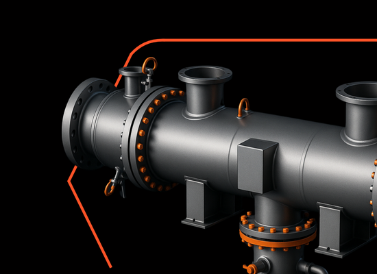
A shell and tube heat exchanger consists of a bundle of parallel tubes enclosed within a cylindrical outer shell. One fluid — the tube-side fluid — flows through the interior of the tubes. A second fluid — the shell-side fluid — flows around the outside of the tubes within the shell. The tube wall forms the heat transfer surface between the two fluids.
Baffles within the shell direct the shell-side fluid across the tube bundle in a series of passes, increasing turbulence and heat transfer efficiency. The number of tube passes — how many times the tube-side fluid traverses the length of the exchanger — can be varied to optimise the thermal performance for the specific duty.
Main Design Types
Fixed Tubesheet
The most common and economical design. Tubesheets at each end are permanently welded to both the tubes and the shell. This design is best suited for applications where the temperature difference between shell and tube fluids is moderate, limiting thermal expansion stress. Cannot be disassembled for mechanical shell-side cleaning.
U-Tube
Tubes are bent into a U-shape and fixed to a single tubesheet. The U-tube bundle can be removed from the shell for inspection and cleaning, making this design suitable for fouling applications on the tube side. Widely used in steam heating, process heating, and power generation applications.
Floating Head
One tubesheet is fixed; the other ‘floats’ — it is free to move axially to accommodate differential thermal expansion between the shell and tube bundle. This design handles large temperature differences and allows the tube bundle to be fully removed for inspection and cleaning on both sides. Preferred for critical process applications and high-temperature differentials.
Key Advantages of Shell and Tube Heat Exchangers
- High pressure and temperature capability — standard designs handle pressures to 300+ bar and temperatures exceeding 400°C
- Robust and well-understood — decades of design codes (TEMA, ASME, PED) provide a well-established engineering framework
- Wide range of materials — tubes and shells can be specified in carbon steel, stainless steel, titanium, Hastelloy, duplex, and other alloys for challenging fluid compatibility requirements
- Large capacities — can be built to handle very high flow rates and heat duties beyond what plate exchangers can accommodate
- Handles two-phase flow — suitable for steam condensers, reboilers, and evaporators in process applications
- Ease of maintenance — U-tube and floating head designs allow complete tube bundle removal
Limitations
- Larger footprint than plate heat exchangers for equivalent duty
- Lower thermal efficiency per unit volume — multiple passes and baffles improve this but cannot match the corrugated plate geometry
- Higher initial cost for small-to-medium duties compared to brazed or gasketed plate exchangers
- Fixed-tubesheet designs cannot be mechanically cleaned on the shell side
Applications
Shell and tube heat exchangers are the standard choice for:
- Oil refining — crude preheat trains, product coolers, overhead condensers
- Chemical and petrochemical processing — reactor feed/effluent exchangers, solvent recovery, product heating and cooling
- Power generation — feedwater heaters, condenser cooling, lube oil coolers
- Pharmaceutical — process fluid heating and cooling, WFI (water for injection) systems
- Marine and offshore — seawater cooling, lube oil coolers, HVAC
- Industrial gas processing — gas cooling, condensate separation
Shell and Tube vs Plate Heat Exchangers: When to Choose Each
| Criterion | Shell & Tube | Plate Heat Exchanger |
| Operating pressure | Up to 300+ bar | Up to 45 bar (140 bar for CO2 BPHEs) |
| Operating temperature | Up to 400°C+ | Up to 225°C (BPHEs) |
| Compact design priority | Lower priority | High priority |
| Mechanical shell-side cleaning | U-tube and floating head designs | Gasketed plate & frame only |
| Expandable capacity | No — requires new unit | Yes — add plates (gasketed) |
| Corrosive or exotic fluids | Wide alloy selection available | Limited to available plate alloys |
| Typical industries | Oil, gas, chemical, power | HVAC, food, pharma, refrigeration |
Explore HEXONIC’s industrial and custom shell and tube heat exchangers — engineered for demanding process applications.
Contact our team for a custom quotation.
Frequently Asked Question
What is TEMA and why does it matter for shell and tube heat exchangers?
TEMA (Tubular Exchanger Manufacturers Association) is the primary design and manufacturing standard for shell and tube heat exchangers. TEMA defines three classes — R (refinery), C (commercial), and B (chemical) — each with progressively less stringent construction requirements. Specifying the correct TEMA class is important for ensuring the exchanger meets the pressure, temperature, and service life requirements of the application.
What is the difference between TEMA R, C, and B classification?
TEMA R is the most stringent classification, specified for the demanding conditions of petroleum refinery service. TEMA C is intended for general commercial and process applications. TEMA B applies to chemical process service. The classes differ in wall thickness, nozzle reinforcement, baffle design, and other construction details.
Can HEXONIC supply custom shell and tube heat exchangers?
Yes. HEXONIC engineers and manufactures custom shell and tube heat exchangers for a wide range of industrial and process applications. Contact the HEXONIC engineering team with your process data sheet (duty specification) for a custom proposal.